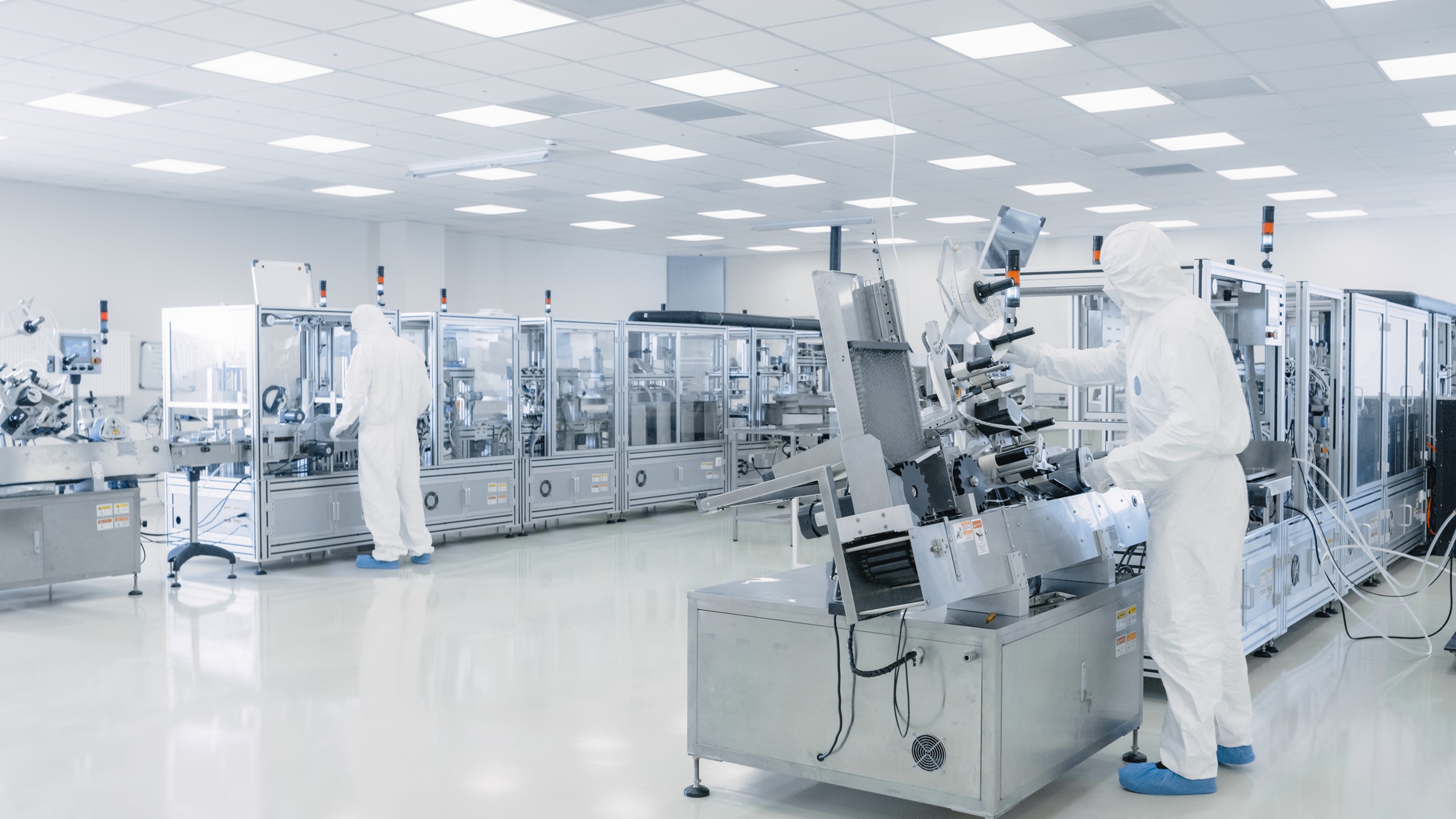

Controlled manufacturing environments, from semiconductor fabrication to electronics assembly to precision optics production, impose strict humidity requirements alongside the particulate cleanliness standards that define their classification. In clean rooms, uncontrolled humidity affects process materials directly: photoresists change viscosity and adhesion behavior, substrates absorb or release moisture that alters dimensional stability, electrostatic discharge risk increases at low humidity, and outgassing rates from process materials change with atmospheric moisture content. In dedicated dry rooms, the requirement is more fundamental: the materials being processed are hygroscopic, and even small deviations from target moisture levels affect bond strength, coating adhesion, chemical reactivity, or product shelf life.
The humidity requirements for controlled manufacturing vary widely by application. Electronics assembly and surface mount technology areas typically require 30 to 50 percent relative humidity to control static discharge while avoiding condensation on components. Semiconductor lithography areas may require tighter control, holding relative humidity to plus or minus 1 percent of setpoint to prevent dimensional variation in photoresist processes. Optical coating and precision lens assembly require low humidity to prevent condensation on substrates during coating and to control film adhesion properties. Aerospace and defense manufacturing dry rooms for adhesive bonding and composite layup require low dew points to ensure bond integrity and prevent moisture entrapment in laminated structures.
What these environments share is that humidity variation is a process variable with measurable product consequences, and the tolerance is typically tighter than what a standard HVAC system can maintain. A clean room rated ISO 7 for particulate contamination may simultaneously require humidity control to plus or minus 3 percent relative humidity, and the air handling system that achieves the particle count doesn't automatically achieve the humidity specification.
Clean room air handling systems are designed to move very large volumes of air through HEPA filtration at high air change rates. An ISO 7 clean room may operate at 60 or more air changes per hour through ceiling-mounted HEPA or ULPA filters. An ISO 5 clean room in a unidirectional flow configuration typically operates at 240 to 480 air changes per hour, with some designs reaching 600. These air change rates are driven by particulate control, not by thermal or humidity loads. The air handling system provides cooling and humidity control as secondary functions of the same supply air stream.
The problem with relying on the cooling system for precise humidity control is that it modulates cooling capacity in response to sensible load, and humidity rides along as a secondary variable. At high air change rates, the makeup air volume is substantial, and during summer peak conditions, the outdoor air moisture load can push supply air humidity above the process specification even when the cooling system is running at full capacity. During low-load conditions, the system modulates cooling down and humidity control loosens. In a clean room requiring plus or minus 3 percent relative humidity, the humidity excursion from a single cooling system modulation cycle may exceed the entire allowable tolerance band.
For dry rooms requiring dew points below 32 degrees Fahrenheit, cooling-based systems are physically unable to reach target. As with any application requiring dew points below what a practical cooling coil temperature can achieve, desiccant dehumidification becomes the necessary technology.
A rotary desiccant wheel delivers precise, continuous dew point control independent of the temperature control system. For clean room applications requiring moderate humidity control (30 to 50 percent relative humidity with tight tolerance), the desiccant system treats incoming ventilation air to a controlled dew point before it enters the clean room air handler. The air handler manages temperature (sensible load) and filtration; the desiccant system manages moisture content (latent load). Because the two systems operate independently, neither is compromised by the other's control response. For dry room applications requiring low dew points (below 32 degrees Fahrenheit, or below -20 degrees Fahrenheit for the most demanding processes), the desiccant system handles all of the latent load and the cooling system handles only the sensible load. The two operate independently: the desiccant system controls dew point, and the cooling system controls temperature.
The critical advantage in precision manufacturing is stability. A well-tuned desiccant system with PID-controlled reactivation holds supply air dew point to plus or minus 1 to 2 degrees Fahrenheit of setpoint continuously, regardless of outdoor conditions, production load, or air handler modulation. That stability translates directly to process humidity stability in the controlled space. For semiconductor lithography, where dimensional accuracy depends on consistent atmospheric conditions, steady dew point control is a process requirement with yield implications. For electronics assembly, where ESD sensitivity demands a specific humidity band, stable control prevents both the low-humidity static events and the high-humidity condensation events that damage components.
ASHRAE Applications (Chapter 19) addresses clean room design and identifies humidity control as a critical parameter alongside temperature and particulate cleanliness, noting that independent humidity control through desiccant dehumidification provides the precision and stability that cooling-based systems cannot match in high-air-change-rate environments.
The standard approach uses the cooling system to overcool the process airstream to its practical dew point floor of 40 to 45 degrees Fahrenheit, reheating the supply air with hot gas or a primary energy source to reach delivery temperature, then adds a standalone desiccant system with separately purchased reactivation energy to reach the final target. Both systems serve the same space but don't share energy or infrastructure.
Desiccant Air Solutions integrates the two systems. A chilled water or DX pre-cooling coil ahead of the desiccant wheel removes the bulk of the moisture load through condensation at the chiller's operating efficiency, which is substantially better per unit of moisture removed than desiccant adsorption at equivalent conditions. The desiccant wheel then polishes the air to the final target dew point, operating with a reduced moisture load and lower reactivation temperature. When additional reactivation capacity is needed beyond recovered heat, the system can also draw from electricity, natural gas, steam, or hot water. When condenser heat is available, it provides reactivation energy that would otherwise be rejected to atmosphere, improving overall system efficiency.
Unlike catalog equipment designed for general-purpose dehumidification, Desiccant Air Solutions engineers each system for the specific process conditions and moisture loads of the application. Wheel media selection, pre-cooling capacity, reactivation temperature, and control logic are all configured for the target environment rather than selected from a standard product line.
System controls use PID logic with dew point sensor feedback to modulate moisture removal continuously. Standard configurations include BMS integration for remote monitoring, alarm management, and setpoint adjustment.
For the most demanding dry room applications requiring dew points below -20 degrees Fahrenheit, staged DX pre-cooling plus two-stage desiccant with heat recovery is the configuration that reaches target at a sustainable operating cost. Single-stage desiccant with electric reactivation can reach these dew points in small systems, but at production scale the energy cost without heat recovery becomes a material factor in operating economics.
Sizing for controlled manufacturing environments starts with two independent calculations: the outdoor air moisture load and the process-area-specific moisture sources. The outdoor air load depends on the makeup air volume (which can be significant in pressurized clean rooms), the outdoor design conditions, and the target supply air dew point. Process moisture sources vary by application: adhesive curing releases solvents and moisture, cleaning operations introduce water vapor, personnel contribute metabolic moisture, and material airlocks admit ambient air during transfers.
A practical starting point for clean room applications: determine the makeup air volume from the pressurization requirement (typically 10 to 15 percent of total supply air), multiply by the outdoor air moisture content at summer design conditions, and subtract the target supply air moisture content. For a 10,000-square-foot ISO 7 clean room with 60 air changes per hour and 10 percent makeup air, supply airflow is approximately 100,000 cubic feet per minute, of which 10,000 cubic feet per minute is outdoor makeup air requiring treatment. At 78 degrees Fahrenheit and 60 percent relative humidity, that outdoor air carries 86 grains per pound; targeting 45 percent relative humidity at 68 degrees Fahrenheit requires supply air at 46 grains per pound, a 40-grain-per-pound reduction across 10,000 cubic feet per minute.
| Environment Type | Target Humidity | Dew Point Equivalent | Key Sizing Drivers |
|---|---|---|---|
| ISO 7 clean room (electronics) | 30–50% RH, ±3% | 38–52°F | OA makeup, personnel, process |
| ISO 5 clean room (semiconductor) | 40–45% RH, ±1% | 43–47°F | OA makeup, photoresist outgassing |
| Dry room (adhesive bonding) | Below 10% RH | Below 20°F | OA makeup, adhesive cure off-gassing |
| Dry room (composite layup) | Below 30% RH | Below 35°F | OA makeup, prepreg out-time moisture |
| Optical coating / assembly | 25–40% RH | 30–42°F | OA makeup, substrate outgassing |
For dry rooms, airlock design and personnel protocols are critical sizing factors. Every airlock cycle admits a pulse of ambient air that the system must process back to target. At very low dew points, a single poorly managed airlock can represent a larger moisture load than all other sources combined. Design the airlock volume, cycling rate, and interlocking logic alongside the dehumidification system, not as an afterthought.
Controlled manufacturing environments impose humidity requirements because the products built in them respond to atmospheric moisture in measurable, consequential ways. A desiccant dehumidification system that separates moisture control from temperature control, integrated with existing cooling infrastructure for pre-conditioning and heat recovery, delivers the stability and precision that these processes require at sustainable operating cost. The HVAC system that controls particles and temperature doesn't inherently control humidity with the precision the process demands. Dedicated desiccant humidity control fills that gap. Contact Desiccant Air Solutions at [email protected] to discuss sizing, system configuration, and integration with your existing clean room or dry room infrastructure.
Desiccant Air Solutions designs and builds custom dehumidification systems combining cooling and desiccant technology for demanding industrial applications. Contact us at [email protected].

2026
Moisture trapped in a lithium-ion cell during assembly doesn't show up until the cell is in service. By then it's a warranty claim, a field failure, or worse.... Read more

2026
Condensation grows mold. In a brewery, every surface that stays wet after sanitation is a potential colonization site, and... Read more

2026
Ice buildup on floors, product, and dock doors is a safety hazard and an operating cost. Cold storage dehumidification elimin... Read more